
📋 Article outline
The first question in any conversation about a charging station is always "how many kW is the charger?". Fair, but not sufficient. The number printed on the label — 14 kW, 80 kW, 160 kW — is the maximum power the equipment can deliver, not the speed a given vehicle will actually receive. The gap between those two figures determines how many sessions a station can serve each day. This article reads the specification sheet of the Scharge charger line — a brand belonging to SPT (Saigon Postel), distributed and deployed as infrastructure by CD Restop — from the perspective of the person who has to make the decision.
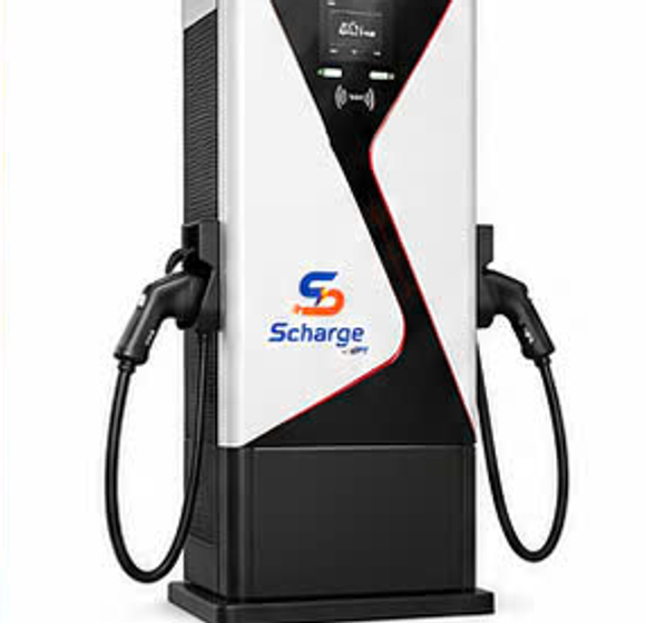
Rated power on the label is a ceiling, not a speed
A DC charger does not decide how much energy it puts into the vehicle. The battery management system (BMS) on board is the party giving the orders: it continuously requests a voltage and a current, and the charger only complies within its capability. If the BMS asks for 90 A, a 160 kW charger delivers exactly 90 A. The BMS issues those commands based on:
- The charging curve. Peak power is sustained only across a narrow band — typically from roughly 10% to 50–60% state of charge — then tapers off to protect the battery. That is why commercial specifications always quote "10–80%": the final stretch is deliberately slow, and no charger can shorten it.
- Current state of charge. A vehicle arriving at 60% draws markedly less power than one arriving at 15%. Same infrastructure, same time window, different energy sold depending on driver habits.
- Battery temperature. Too hot or too cold and the BMS limits current. In Vietnam the common case is a battery heated after a long highway leg or several consecutive fast-charging sessions.
- The nominal voltage of the battery pack — the most important factor, and it deserves its own section.
The charger does not "push" energy into the vehicle. The vehicle "pulls" energy from the charger, within the limits the charger allows. Choosing a charger means choosing a ceiling — which only matters when that ceiling sits above the real demand of the fleet that will use it.
The 250 A per-connector limit: 800 V vehicles benefit, 400 V vehicles do not
Scharge specifies a maximum output current of 250 A for chargers up to 160 kW and 300 A for the 200–400 kW range, with an output range of 200–1000 V DC on a 1000 V platform. Together these form a physical constraint no software can overcome: power equals voltage times current.
A vehicle with a battery pack of around 400 V — the most common configuration today — operates in the 350–420 V band. Multiplied by the 250 A ceiling, theoretical maximum power comes to only about 90–105 kW. In other words, plug that vehicle into a 160 kW DC charger and it still levels off around the 100 kW mark, even though the charger has power to spare; against an 80 kW DC charger the real-world difference is only about a quarter — not "twice as fast" as the names suggest. The picture reverses for vehicles built on a roughly 800 V battery architecture: an operating voltage of 650–800 V multiplied by 250 A leaves headroom well beyond 160 kW, so the vehicle uses almost the full ceiling of the charger. This is also why new-generation models are moving to higher-voltage platforms — to transfer the same power at lower current, reducing heat generation in cables and connectors.
The conclusion is not "do not buy a 160 kW charger", but that power must be selected according to the profile of the fleet the station will serve and the roadmap for the next 5–10 years. A station on a freight corridor, where electric trucks and buses are the main customers, extracts the full value of a high-power charger. A residential station serving privately owned 400 V vehicles leaves that surplus power idle, while the electrical infrastructure behind it still has to be paid for in full.
Two connectors, one power block
The SC80 line (80 kW DC) has two connectors with a clearly stated mechanism: one connector takes the full 250 A maximum current, or both connectors split the power when operating at the same time. This shared architecture makes economic sense, but it has to be understood correctly at the design stage: precisely at peak hours — when the station most needs throughput — each vehicle receives less than it would when the site is quiet.
- Two shared connectors on one charger: lower cost per charging point, smaller footprint, fewer connection points. Suitable where traffic is spread across the day.
- Two independent chargers: every vehicle always gets full power, at the cost of a correspondingly larger contracted capacity with the utility and heavier low-voltage infrastructure. Suitable for commercial fleets with clustered schedules — taxis changing shifts, delivery vehicles returning to the yard within the same time window.
For larger station clusters the answer is usually dynamic load management: real-time allocation across chargers, prioritising vehicles about to depart or running low, while keeping total load within the contracted limit. This is one of the four components agreed by the CD Restop – Scharge – SPT alliance: low-voltage electrical works, rooftop solar, BESS storage and smart chargers under centralised load management. BESS allows a station to absorb a surge of arrivals without raising contracted capacity to a level used only a few hours a day.
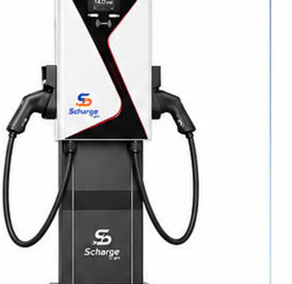
14 kW AC: the right choice for the right place, not the cheap choice
With AC charging, the AC-to-DC conversion happens on the vehicle — in the onboard charger; the unit only supplies alternating current and handles safety control. AC charging power is therefore limited by each vehicle's onboard charger, not by the charging unit: a vehicle with a 7 kW onboard charger draws only 7 kW even when plugged into a 14 kW unit. In exchange, the SC14 with two connectors and a maximum current of 64 A serves two vehicles at once at a level most onboard chargers today can accept.
AC is right wherever parking time exceeds the time needed to charge: hotels and accommodation at rest stops (vehicles park for 8–10 hours and the battery is full by morning — installing DC here means leaving an expensive asset idle all night); apartment buildings (the charging cycle matches the sleep cycle, and low current puts less thermal stress on the battery than repeated daily fast charging); offices and daytime car parks (ideal locations to pair with rooftop solar under a self-generation, self-consumption model); fleet staging yards charging overnight during off-peak hours. In short: DC buys time, AC buys charging points. For a lot holding 30 vehicles overnight, covering every space with AC solves the problem more thoroughly than a handful of DC chargers with drivers rotating through them.
Multi-standard connectors: the cost of a market that has not converged
Scharge simultaneously supports CCS1, CCS2, GB/T and CHAdeMO on the DC side and Type 1 and Type 2 on the AC side. These standards emerged market by market: CCS2 with vehicles designed for Europe, CCS1 and Type 1 with North America, GB/T with the Chinese market, CHAdeMO with earlier-generation Japanese models. Electric vehicles on Vietnamese roads come from many sources — assembled domestically, imported from several markets, and purpose-built commercial vehicles — so no single standard covers them all.
The economic consequence is direct: every missing standard is a customer segment shut out of the station. A charger with CCS2 alone turns away every GB/T vehicle passing by — and for commercial vehicles, GB/T cannot be ignored. A multi-standard configuration is therefore insurance across an 8–10 year asset life while the market has yet to converge. One detail often overlooked in site layout: the custom 5 m charging cable. Charging port positions vary widely between vehicles; a short cable forces drivers to park in one orientation, while a cable of sufficient length allows any approach — at a station serving passing traffic, that difference feeds straight into turnaround time.
IP54, −25…50℃ operating range, sheet-steel enclosure, 95.5% efficiency
IP54 and the operating temperature range
IP54 means limited dust ingress and protection against water splashing from any direction — suitable for outdoor installation in heavy rain with wind-driven spray, and for hosing down the forecourt. What IP54 does not cover is immersion, so station design must include a plinth raised above yard level, drainage channels of adequate cross-section, and absolute avoidance of low-lying spots with a history of flooding. This is where a site survey delivers the most value — the reason CD Restop puts the survey step ahead of any configuration proposal.
With a range of −25℃ to 50℃, the cold end is all but irrelevant in Vietnam; the hot end is very relevant. 50℃ is the ambient temperature, not the temperature of a concrete apron baking in the afternoon sun. As it approaches that ceiling, the cooling system has to work harder and the charger may derate itself to protect its components. The three remedies — a canopy, an orientation that avoids the afternoon sun, ventilation clearance — are inexpensive, but they must be decided at the design stage; they cannot be retrofitted once the foundation is poured.
Sheet-steel enclosure, efficiency and input supply
Sheet steel withstands impact far better than plastic — which matters in a car park where a knock while reversing is routine — and does not become brittle under ultraviolet exposure; in exchange it needs an anti-corrosion coating maintained on a periodic service schedule, especially at coastal stations. With efficiency of 95.5% (up to 160 kW) and 94% (200–400 kW range), the remaining percentage turns into heat: on a 160 kW charger running at high load, the heat to be dissipated is significant and continuous — which explains why high-power chargers come with correspondingly sized cabinets and cooling systems, rather than being simply "a small charger doubled". That loss sits on the grid input side and is counted as energy purchased under the applicable utility tariff, while what is sold to the customer is the energy actually delivered into the vehicle.
An input range of AC 380 V ±15% / 50 Hz (or AC 220 V ±15%) is a tolerance for grids that fluctuate, common outside urban centres. But tolerance is no substitute for supply quality: if the voltage regularly touches the limits, the correct fix lies on the low-voltage side — the transformer station, cable cross-sections, the distribution board.
Accuracy class 1 metering
Scharge chargers use accuracy class 1 metering — error within ±1% under rated operating conditions. On paper this is a single line of specification; in commercial operation it is the foundation of the customer relationship. Customers pay for the kWh delivered; if the measurement cannot be trusted, invoices get disputed, revenue reconciliation between parties fails to match, and driver confidence erodes faster than after any technical fault. In models with revenue sharing between the site owner and the operator, meter accuracy is the basis on which both parties reconcile each month without argument.
Accurate metering only pays off when the data can get out. Chargers connect over Ethernet, 4G or 3G — in the alliance model, transmission relies on SPT's telecommunications infrastructure — and push session data to a centralised management platform. Only then do electronic invoices, session history retrievable in the app, and flexible payment become possible: QR code, card, VIN recognition, or in-app. OTA software updates on an IoT platform allow bugs to be patched and features added without sending a technician to site — a decisive factor for operating cost as the network expands.
Which charger for which situation
- Hotels and rest-stop accommodation — 7/14 kW AC, prioritising coverage across many charging points over a few high-power ones.
- Apartment buildings, offices, monthly parking — AC is the primary choice; pair with solar if it is a daytime car park. Consider adding one 40–80 kW DC charger for urgent top-ups.
- Highway-side stations serving passing private vehicles — 80 kW DC with two connectors is the balance point, enough for a 20–30 minute top-up; multi-standard connectors are mandatory.
- Freight corridors, electric trucks and coaches — 160 kW DC and above. Large batteries, many high-voltage models, and dwell time is a direct cost to the operator. This is where the power ceiling is genuinely used.
- Bus, truck and logistics depots — two layers: high-power DC for mid-shift top-ups, AC across the whole yard for overnight charging during off-peak hours.
- Ride-hailing taxi and delivery fleets — 80–160 kW DC, but the decisive factor is the number of independent chargers rather than the power of each, because vehicles return in shift clusters.
- Commercial complexes — a mix: a few DC chargers in visible positions for short visits, plus AC in long-stay parking areas. A charging station is both a service and an anchor for footfall.
In every case, the charger configuration is only the final layer. The three layers beneath it — the low-voltage capacity contracted with the utility, the capacity to add on-site solar, the storage system that balances load — determine how far a station can grow without being torn down and rebuilt. That is why the four investment components are designed as one from the outset, with capacity headroom for 5–10 years, rather than installing chargers first and chasing power upgrades later.
Contact
Three forms of cooperation are currently offered: outright purchase and self-operation — the partner buys genuine chargers and installs them on their own site, CD Restop handles installation, app activation and warranty, and the partner keeps all charging revenue; joint investment and operation — the partner contributes the site and the transformer station, CD Restop invests in the chargers, construction, software and operation, and both parties share actual monthly revenue as agreed; corporate charging stations — a turnkey package for the electric fleets of transport, delivery and ride-hailing companies under a service contract.
Choosing a configuration should start from the site, not from a catalogue. A three-step process: send your requirements → CD Restop surveys the site and proposes a suitable configuration → agree the model, sign and deploy. Point of contact: hi@cdrestop.com. Full technical specifications are published at cdrestop.com/vi/scharge; commercial terms and quotations are provided per specific case after the survey step.
See the specifications of each charger model on the Scharge products page.